Networking Basics: TCP, UDP, TCP/IP and OSI Model
Networking basics- TCP, UDP, TCP/IP & OSI Model
Networking Basics:
TCP, UDP, TCP/IP and OSI Model
The Transmission Control Protocol/Internet Protocol (TCP/IP)
suite was created by the U.S. Department of Defense (DoD) to ensure
that communications could survive any conditions and that data integrity
wouldn’t be compromised under malicious attacks.
The Open Systems Interconnection Basic Reference Model (OSI Model) is an abstract description for network protocol design, developed as an effort to standardize networking.
In this article, I will present the differences between the DoD and the
OSI models and then provide details about the DoD’s version of TCP/IP. I
will also describe the protocols used at the various layers of the DoD
model and provide you with the details of TCP and UDP protocols.
Throughout this article you will find useful information concerning the
protocol suite of the century: TCP/IP.
TCP/IP and the OSI Model Comparison
Let’s Start by Comparing TCP/IP and the OSI Models. The TCP/IP model is
basically a shorter version of the OSI model. It consists of four
instead of seven layers. Despite their architectural differences, both
models have interchangeable transport and network layers and their
operation is based upon packet-switched technology. The diagram below
indicates the differences between the two models:

- Application Layer: The Application layer deals with representation, encoding and dialog control issues. All these issues are combined together and form a single layer in the TCP/IP model whereas three distinctive layers are defined in the OSI model.
- Host-to-Host: Host-to-Host protocol in the TCP/IP model provides more or less the same services with its equivalent Transport protocol in the OSI model. Its responsibilities include application data segmentation, transmission reliability, flow and error control.
- Internet: Again Internet layer in TCP/IP model provides the same services as the OSIs Network layer. Their purpose is to route packets to their destination independent of the path taken.
- Network Access: The network access layer deals with all the physical issues concerning data termination on network media. It includes all the concepts of the data link and physical layers of the OSI model for both LAN and WAN media.
The diagram below shows clearly the way TCP/IP protocol suite relates to the TCP/IP model.
Host-to-Host Layer Protocols
Two protocols: Transmission Control Protocol (TCP) and User Datagram Protocol (UDP)
are defined for transmitting datagrams. We will look at the details of
both these protocols as well as their interaction with the upper layer.
Transmission Control Protocol (TCP)
TCP is connection-oriented in the sense that prior to transmission end
points need to establish a connection first. TCP protocol data units are
called segments. The sending and receiving TCP entities exchange data
in the form of segments, which consist of a fixed 20-byte header
followed by a variable size data field.
TCP is responsible for breaking down a stream of bytes into segments and
reconnecting them at the other end, retransmitting whatever might be
lost and also organizing the segments in the correct order. The segment
size is restricted by the maximum transfer unit (MTU) of the underlying
link layer technology (MTU is generally 1500 bytes which is the maximum
payload size of the Ethernet).
The image below shows the TCP segment format. The most important fields are explained further on.
- Source Port and Destination Port fields together identify the two local end points of the particular connection. A port plus its hosts’ IP address forms a unique end point. Ports are used to communicate with the upper layer and distinguish different application sessions on the host.
- The Sequence Number and Acknowledgment Number fields specify bytes in the byte stream. The sequence number is used for segment differentiation and is useful for reordering or retransmitting lost segments. The Acknowledgment number is set to the next segment expected.
- Data offset or TCP header length indicates how many 4-byte words are contained in the TCP header.
- The Window field indicates how many bytes can be transmitted before an acknowledgment is received.
- The Checksum field is used to provide extra reliability and security to the TCP segment.
- The actual user data are included after the end of the header.
Let’s have a look at how a TCP segment is captured by Ethereal network
analyzer. The image below shows a request-response message sequence
carried over TCP. Notice the fields discussed above: Source Port,
Destination Port, Sequence number, Acknowledgement number, Window size
and checksum.
User Datagram Protocol (UDP)
UDP protocol consists of fewer fields compared to TCP. The reason for
that is because certain data types do not require reliable delivery and
extra overhead. Real-time traffic for example, needs to be transported
in an efficient way without error correction and retransmission
mechanisms.
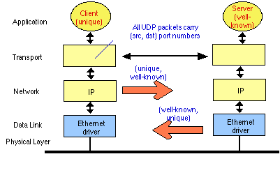
UDP is considered to be a connectionless protocol. It leaves reliability
to be handled by the application layer. All it cares about is fast
transmission. The UDP segment format is presented in the diagram below:
Let’s see how a UDP segment is captured by Ethereal. Notice the small header size.
Which One Should You Use?
Choosing the right transport protocol to use depends on the type of data
to be transferred. For information that needs reliability, sequence
transmission and data integrity — TCP is the transport protocol to use.
For data that require real-time transmission with low overhead and less
processing — UDP is the right choice.
The following table summarizes the key-characteristics of each one of
these protocols. Keep them in mind when choosing the transport protocol
for your data.


No comments: